DAQ Pad
o Set the DAQPad settings by clicking Settings > Select Input Device > DAQPad settings
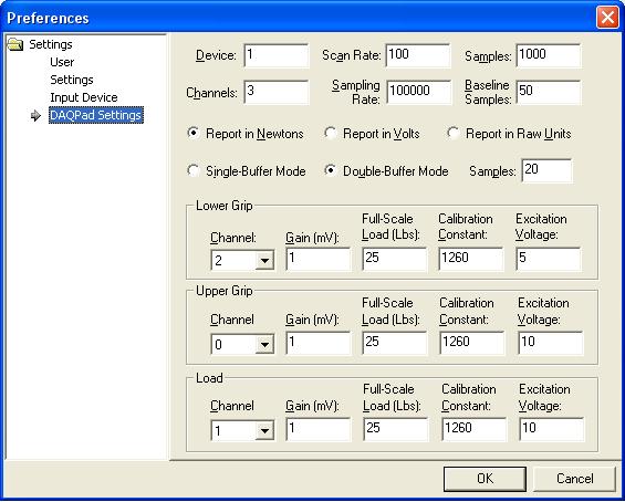
o Device=1: To use the gripper device by Neuroscript, this device number should be set to 1, otherwise, use the device number that is configured by Measurement and Automation Explorer as below.
NOTE: Start the Measurement & Automation Explorer that comes with the NIDAQPad driver. Mysystem > Devices and Interfaces > DAQPad6020E > right click > properties > Check the device number. For the gripper device, set it to 1 if it's not set to that already. In other devices, update the Movalyzer device settings with the device number used in DAQPad.
o #Channels=3: For the gripper device set the number of channels to 3. In other devices, set this as the number of channels to be scanned for input from the DAQPad.
o Scan Rate=100 (Hz): The scan rate is comparable to the digitizer sampling rate.
WARNING: Setting the scan rate very high, example 500 Hz will result in the loss of sampling points and empty processed data files. During processing of the trial (by default, after recording the trial), warning messages are displayed in the results window (and eventually actions.log file), when this happens and any further processing/recording of data is terminated. Also a message that the corresponding .SEG file is missing might be displayed after recording the first trial.
NOTE: During processing, this scan rate should be entered under Input Device Settings Sampling Rate. Right-click the particular experiment > Experiment Settings > Recording > Input device > Sampling rate=200 Hz.
o Sampling Rate=100000 (Hz): This is the rate of sampling BETWEEN the channels and is chosen maximally.
o #Samples: (per trial) The duration (s) of a trial is equal to #Samples/Sampling Rate (Hz).
For example, if you want to run a trial for 10 sec and the sampling rate is 100Hz, then the number of samples should be set to 10*100 = 1000 samples in the input device settings.
These settings are per user, hence, each time the user runs a new experiment, verify that the number of samples will satisfy the duration/trial for the new experiment.
o #Baseline Samples is the initial number of samples to calibrate the current zero levels for all Gripper sensors. NOTE: During that time, the Gripper should be at rest and not touched.
o Report Data type to be stored in the raw data files: Raw DAQpad units, Volts, or Newtons (recommended for gripper).
NOTE: During processing, data should not be converted. Right-click the particular experiment > Experiment Settings > Recording > Input Device > Device resolution=1 N.
o Single Buffer Mode: Data are stored first and then displayed (Single Buffer). #Samples option for double-buffering is disabled in this case.
o Double Buffer Mode:# Samples specified are stored and displayed while the next #Samples are stored in the other buffer (Double Buffer). This allows almost real-time feedback of Gripper recordings. On fast machines, use #Double-buffer samples=10. On slower machines this number should be increased.
o Channel Selection and properties: For Lower Gripper, Upper Gripper and Load force.
The channel selection depends upon the interface card. Gripper III requires Lower Grip=Channel 1, Upper Grip is Channel 2, and Load is Channel 1.
Manufacturer's test data of the particular sensors (e.g., Entran ELPM-T2E-251*) determine the following settings: Gain=2.5 mV/V, Full Scale=25 Lbs, Calibration=1260, Excitation=5 V.
o Gain (mV/V) is the output voltage under full scale load per Volt excitation. This setting is needed to report voltages or Newtons.
o Full-Scale Load (Lbs) is the maximum calibrated force that can be measured accurately. WARNING: Exposing the sensors to higher forces may result in irreversible damage.
o Calibration Constant is the scale factors expressing N/mV per sensor. In the Gripper, the two grip forces are calibrated for (positive) compression force and the load force for (negative) tension force. The calibration constant increases with the Gripper board's multiplication factor.
o Excitation (V) is the voltage across the sensor. The sensor outputs a voltage that is a fraction of the excitation voltage. This setting is needed to report voltages. The fraction depends on the load. The normal excitation voltages for the gripper are as in the above settings window. WARNING: High excitation voltages may cause irreversible damage.
© NeuroScript LLC. All Rights Reserved.