| NeuroScript MovAlyzeR Help | Send comments on this topic. |
Glossary Item Box
| NeuroScript MovAlyzeR Help | Send comments on this topic. |
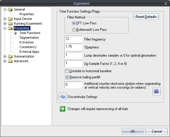
Time Functions: Settings and Flags
Filter Method
The user can specify to filter trial data using an FFT low-pass filter or a 4th-order zero-lag Butterworth low-pass filter.
Filter Frequency The low-pass filter is a frequency domain (using Fast Fourier Transform), low-pass filter with bandpass equal to 1, stop band equal to 0, and overall 0-phase. In principle, it can have any filter characteristic (Teulings & Maarse, 1983), however, a symmetrical, sinusoidal attenuation band is set between Filter Frequency * (1 +- 4 / 7) while only the Filter Frequency can be selected. Refer to the section on filtering for more description.
Sharpness Can also be set to the required level in addition to the filter cut-off frequency. The implication would be that half filter width = filter frequency/sharpness.
Lump decimates samples or 0 for optimal decimation This option reads every Nth sample (where N is specified in the box) instead of reading every sample.
This option can be used to avoid truncation of the recordings when they consist of several thousands of samples.
If you specify decimation value of 0, MovAlyzeR will automatically determine the optimal decimation to analyze the entire recording independent of its size, by first reducing the number of samples and then by averaging into groups of 2, 3, ... samples.
If you as the user want to determine the decimation to have a fixed value, set it to a positive value of 1 (default = no decimation), 2, 3, ..... A good start value is 1, unless truncation takes place in which case you may choose 0.
Up-sample factor (1, 2, 4 or 8) Up-sample the recorded samples for greater accuracy in processing and feature extraction.
Unrotate to horizontal baseline Various kinds of movement patterns can be processed by the program, e.g., One or more strokes with a particular orientation <or> Drawings containing all kinds of strokes <or> Writing patterns with a particular baseline.
To properly analyze these patterns you can segment (See also segmentation) into strokes and submovements and calculate features based on the:
~ Vertical velocity, which requires that the crucial movement component is rotated to vertical (for example, longitudinal velocity in a straight line, letter height in a line of handwriting).
~ Absolute velocity, which does not require rotation.
To "unrotate" the entire recorded movement pattern to a standard direction, 2 parameters were implemented:
~ Estimate the orientation and rotate automatically to 0 degrees. The orientation is estimated by a least squares line across all samples.
~ Rotate a constant angle.
EXAMPLE 1: A long sentence will be rotated to horizontal baseline (0 degrees). Vertical velocity can then be used to segment into successive up and down strokes. The letter height is measured in the vertical direction. Vertical velocity, acceleration, and jerk represent the longitudinal component. Horizontal velocity, acceleration, and jerk represent the orthogonal component, i.e., perpendicular to the movement direction.
EXAMPLE 2: A single stroke movement. To allow segmentation using the vertical velocity, you can rotate +1.5708 radians.
EXAMPLE 3: A multi-stroke drawing with various directions may not have one preferential directory. Absolute velocity should be used to segment. Measures should be used based on absolute size, absolute velocity, absolute acceleration, and absolute jerk.
Remove trailing pen-lift
Points with a zero pressure value at the end of the trial will be discarded during processing. It is set to ON by default for a new experiment.
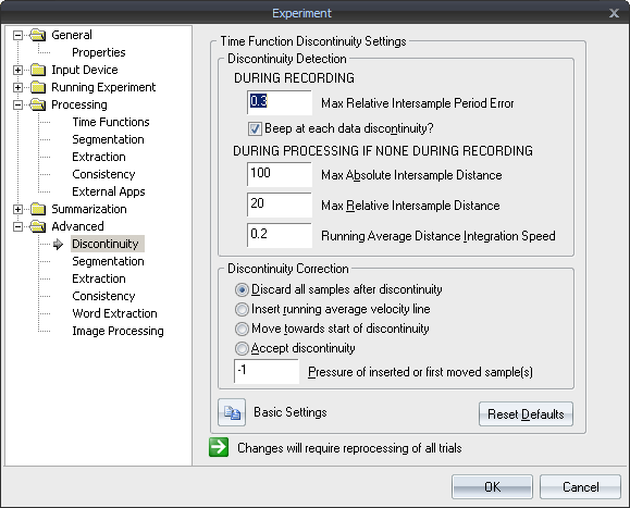
Discontinuity Settings
| See Also |
NSHelp: Filtering Data | Processing Segmentation Settings | Processing Extraction Settings | Word Extraction | Processing Summarization
© NeuroScript LLC. All Rights Reserved.